Trim, slender, beautifully proportioned, sexy little action, fun to look at, and fun to play with. Not only that, this is where it all began, "Lever Guns" that is.

The original Volcanic shot a short little bullet called the "Rocket Ball", it was less than .650" long and had very little power, but this Rifle had the genes to become the legendary Winchester. It goes like this;
- The Volcanic was enlarged to become the "Henry",
- The "Henry" was improved to become the "Winchester 66"
- The 66 was improved to become the "Winchester 73"
- The 73 was enlarged to become the 76.
- And then Mr. Browning came along with a much stronger, smaller action, and replaced the toggle link system, invented by Mr. Smith and Mr. Wesson, which was used in the Volcanics through the 1876.
Above is my design, based on the toggle link system. My design is stronger than theirs, and easier for me to build. While designing this gun, I tried to copy the original dimensions and proportions. I do not have access to an original, so I have had to "scale" photographs to come up with what I have. The first problem I came to was this little action would not shuffle and shuck any available cartridges except the "22 Short"! This did not excite me so I designed my own "Wildcat 40". I will describe it to you later.
This is not a "kit" or a modification of another "Lever Gun". I will not be using purchased parts, or parts from other guns. I will use a purchased barrel blank from "Douglas" (40 Caliber, 1 in 14 twist) cut it, mill it, thread it, and chamber it for this rifle. Everything else, including the springs and most of the screws, I will make from scratch.
 In all my research, I have found this book to be the most informative. That's a Beautiful 20" Volcanic on the cover.
 About the cartridge that I'm shooting, It has been correctly noted that this gun will shuffle, shoot, and shuck the .22 Short, also the (sometimes available) .41 Derringer.
Even though these are an improvement over the original "Rocket Ball", I am not very impressed with either of them. The actual caliber of the #2 Rocket Ball was .41. So that is why I set out to develop my own cartridge.
I figured it like this, if I can't build my own cartridge, then I'm not gonna be able to build this gun.
I do agree somewhat with the guys that would want this gun in .22 Short, it's not for me, but it would make a nice little squirrel gun.
I shortened a 40 S+W case to .550". I reamed out the inside to accept the bullet. The cartridge shown is loaded with Berry's 135 grain copper plated bullet being shoved out of an 8" barrel at 1020 FPS in front of 4 grains of Bullseye. I have fired this Cartridge out of a 25" barrel and lost nearly 100 FPS! I don't like this load as it does show signs of excessive pressure. I have been shooting a 140 grain cast bullet in front of 3.5 grains of "Power Pistol", here I am getting 890 FPS, and visual inspection shows only moderate pressure. The Cartridges are shown in comparison to 22 Long Rifles.
 | OK, let's get started. This is a basic barrel blank by Douglas. It is 1.300" OD. I will put it between centers and turn it end to end, 1.25", and then cut off each end to have a barrel 25.09" long (the rifling is not perfect at the very ends is the reason you cut off both ends.) |
 | Using a center in the tail stock, I single pointed this thread. It is 11/16 - 20 UN X .875" long. |
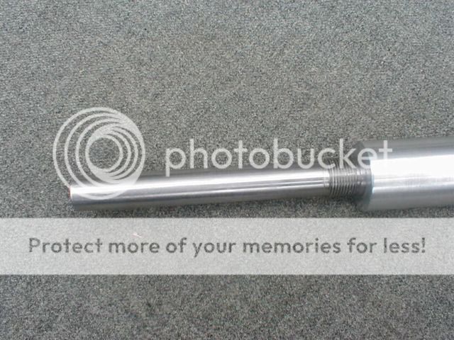 | Turning the barrel around and once again using the tail stock center, I turned this muzzle extension. That is a 11/16-20 left-hand thread you are looking at here, the extension is .624" diameter. |
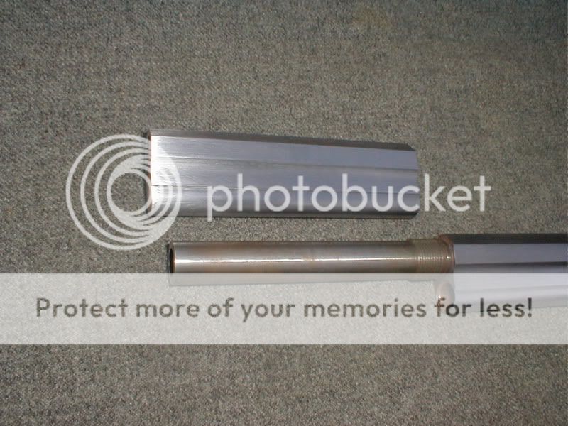
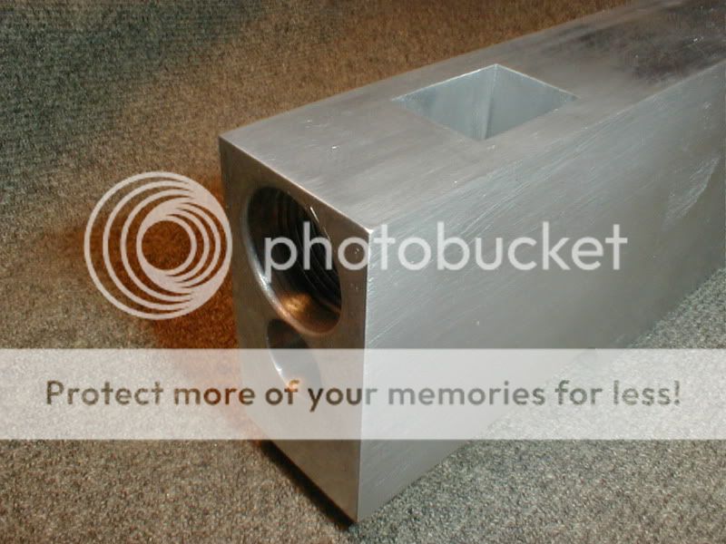
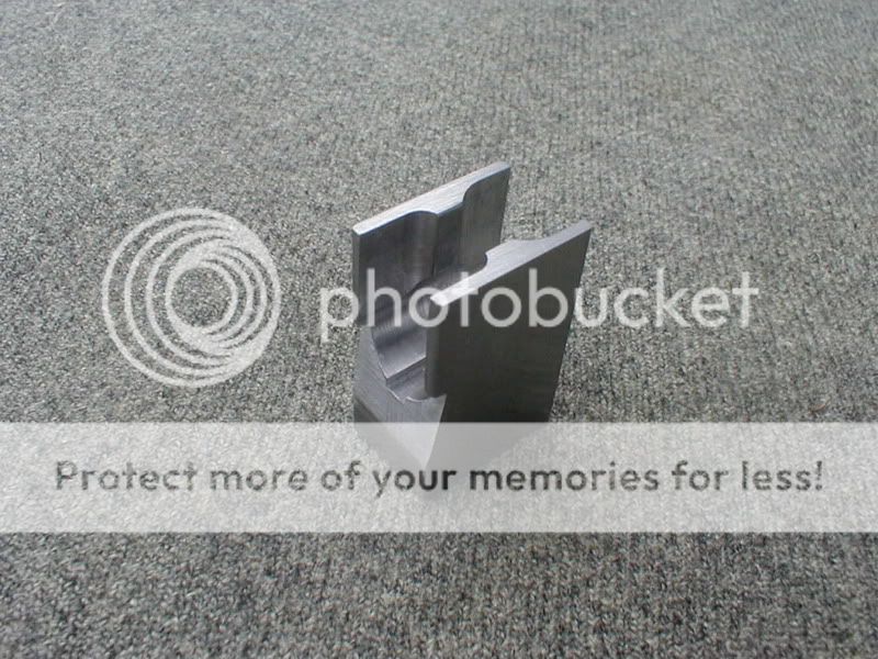
 | Not much to see here, but this is to become the magazine block. It has a drilled and reamed hole through it and that 11/16-20 left hand thread cut in one end. We will thread this over the muzzle extension, and take the assembly to the milling machine where they will get their octagon shape, also a .281" radius trench milled the entire length along the bottom. |
 | I like using a double vice setup when milling long bars like this. This barrel wants to have a slight taper, so I put a .040 shim under the muzzle while milling the flats. This is a picture from a previous barrel, but the idea is the same. |
 | Remember I had threaded the magazine block on the barrel extension and put the entire assembly in the milling machine to mill the outside flats and magazine trench? Well here it is off the milling machine. |
 | Here is a close up of the breech end. |
 | Here is the magazine block removed from the barrel extension. The next thing we need to do is solder the magazine tubes underneath the barrel. |
 | Those magazine tubes were made from 5/8" OD x 7/16" ID, AISI ~ 1018 mechanical tubing. I cut them to length, 5.030" for the magazine block, 19.281" for the barrel. Turned the OD to 0.562", and we are ready to solder. With some good clamps and holding your mouth just right, you can get a good soldering job. I made the clamps shown here from 1/4" x 1" flat bar. I prepared the parts, fluxed them, heated them and applied solder, spread the solder with steel wool over the area that wants to be mated with the other part (both parts), clamped them together with the clamps, layed short lengths of solder (.38" long) every 2" or so on the joint. Heated the entire assembly from underneath until the solder melted and ran down into the joint. Added a little more solder to the joint. Let them cool, removed the clamps, and spent the rest of the afternoon cleaning them up. |
 | Here she is, all soldered together, close-ups to follow. |
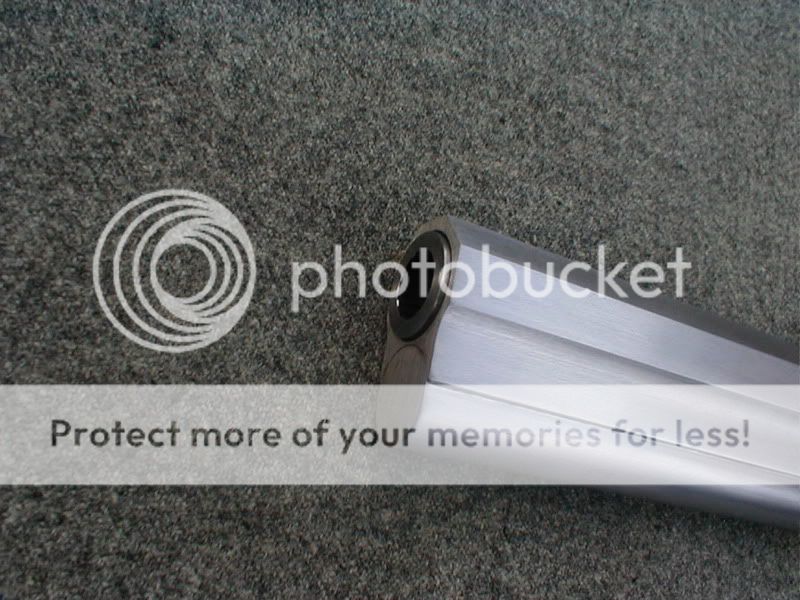 | Muzzle. |
| Original muzzle. | |
 | Breech. |
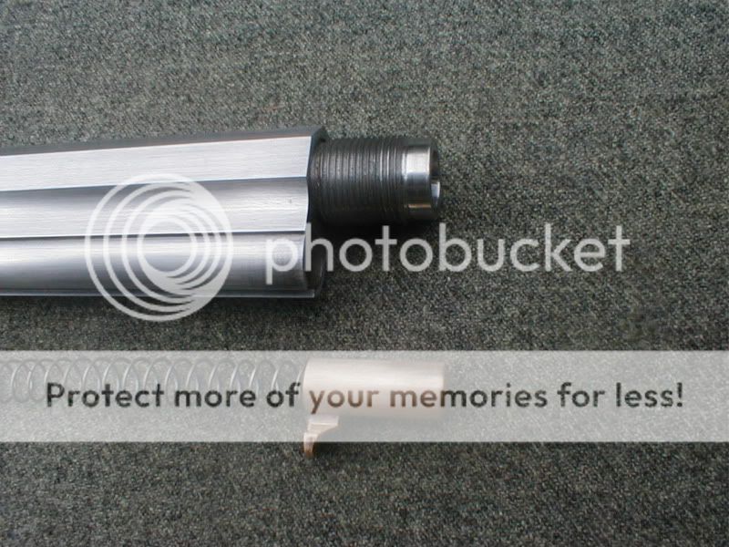
 | Here is the magazine block removed from the barrel. There is a protruding tab under the barrel that is pushed toward the action by a long spring. This spring pushes the cartridges back into the action where they are lifted up and shoved into the chamber by the bolt. To load this gun, this tab is pulled up into the magazine block, compressing the spring in front of it, the magazine block is un-locked and rotated clockwise about 35º exposing the magazine tube for dropping the cartridges into it. This rifle with the 25" barrel will hold 25 shots and one in the chamber. On the original Volcanic and Henry, the magazine block was held on the barrel extension by a collar which had the front sight mounted to it. This collar did not rotate but allowed the magazine block to rotate, it also had a recess milled in the front that served as a stop to limit the rotation of the magazine block. In keeping with the method and spirit of the original, my rifle operates the same as theirs, however, I have designed a different way to retain the rotating magazine block and limit the rotation. My magazine block is held on the barrel extension by this left-hand thread. The thread is timed so that when it is bottomed out, the tubes line up with each other. The reason for the left-hand thread is so that as the magazine block is rotated clockwise, it backs away from the barrel instead of tightening into it. Notice the tube has had a .25" long plug pressed into it, blocking off the front. It has also been bored out to 0.500" to accept the locking sleeve which I have yet to make, or explain how it works. The next thing I will do is mill that slot along the underneath of the barrel, and then make the lock sleeve, then wind a spring and make the cartridge pusher (follower, edit.). |
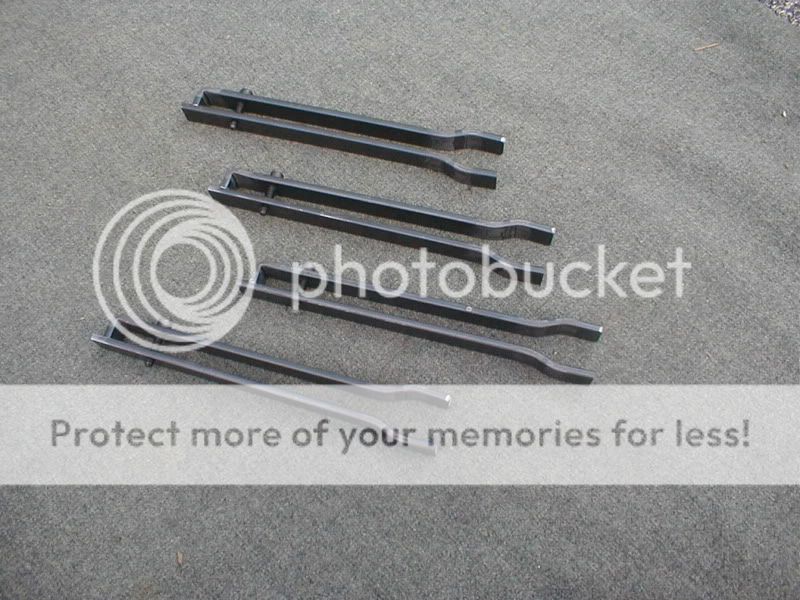
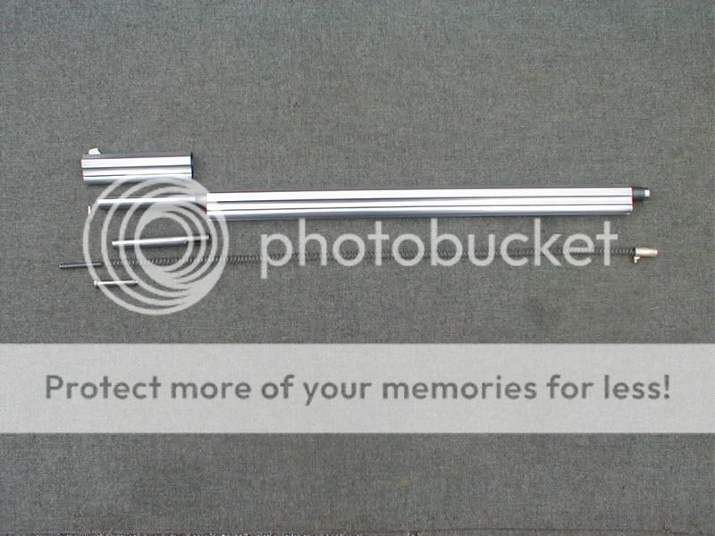 | Here are all the parts that make up the barrel assembly. It is finished, I have milled the slot and made all the required parts. |
 | Here is the magazine block, it has the same outside contour as the barrel, it has a (left-hand thread) inside to match the (left-hand thread) on that barrel extension. It is held on the barrel extension by this thread. The reason for the left-hand thread is so that when it is rotated clockwise it backs away from the barrel instead of camming into it. When it is rotated enough to clear the magazine, it is stopped by that pin with set screw that comes in from the bottom at the front. This pin goes in a slot cut underneath the barrel. This magazine block also carries the front sight, which was soldered in to a slot milled in the top. The tube underneath the octagon carries a sleeve that is continually being pushed back into the magazine by a heavy spring at the front. This tube fits into a shallow recess at the very front of the magazine, locking the magazine block in it's appropriate position. This sleeve is made from O-1 Tool Steel and hardened. The magazine spring was wound from 0.026" spring wire. I wound this spring to fit this particular rifle. If you are thinking that I could have purchased a spring, this might not be as easy as it might first appear because; you see, this spring has to be collapsed entirely in the magazine block, yet be able to expand enough to push a cartridge into the action at the other end of this 25" barrel. |
 | Here is the cartridge pusher (follower, edit.), it is made from a solid piece of aluminum bronze. |
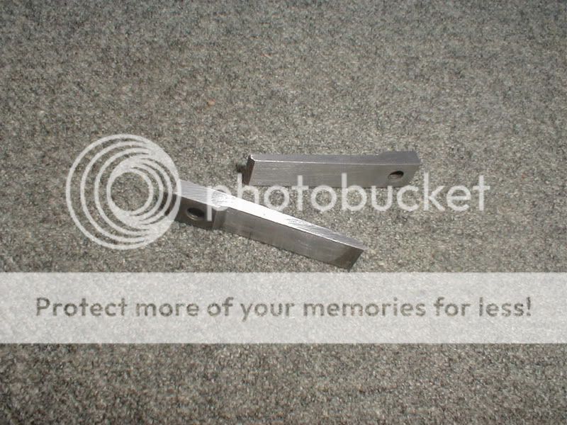
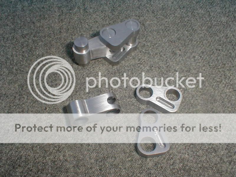 | These are my toggle links and pins. The links are cut from O-1 Tool Steel and hardened. |
 | Here is a toggle bolt assembly useing those links. This is a much stronger design than Smith + Wesson used and the steel is much better also. That is an inertia firing pin like Mr Browning used in the M11, 45 ACP, so the gun can be carried with a cartridge in the chamber and the hammer down. The next thing we will tackle is the receiver, I will make this one out of European, aircraft aluminum. This stuff is strong, about 78K tensile strength, good stuff. The American equivalent would be 7075. I am using aluminum and leaving it's natural color as this mimics the silver plated bronze frames used in the originals. The silver plated frames with the blued barrels were beautiful guns. |
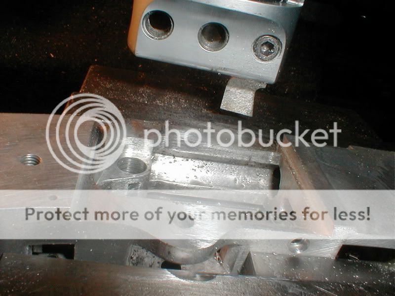
 | The most difficult thing about making this frame is that square hole up front where the cartridge elevator rides. Here I am drilling out the bulk of the metal in preparation to broach this hole manually. I will use the quill of my Bridgeport, using a broach that I ground especially for this job. |
 | Here I am using the broach mentioned above. |
 | Look at that beautiful hole, not bad for an old farm boy, just trying to build a rifle. |
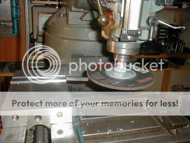 | OK, this is a right angle grinding disk. I made the arbor for it on my lathe. Here I am using my milling machine to do the grinding. |
 | This is what my broaching tool looks like. That long rod sticking out the side is to aid in aligning it up square and parallel with the table. I made the shank of the tool to fit the largest collet I had for stiffness. |
 | Here is the trigger, it is cut from 1/4" O-1 tool steel. I used my little CNC milling machine to cut this baby out. |
 | Here's the hammer cut from 3/8" Tk. ~ O-1 tool steel and hardened. That big hole in the middle of it does 2 things for me, the first is to make it easy to hold down on a fixture while cutting it out, the second is, it lightens it for quicker lock time and more striking energy (it's a physics thing). |
 | The hammer spring is also cut from O-1 and bent to shape before hardening. Springs should be hardened above 42 RC. |
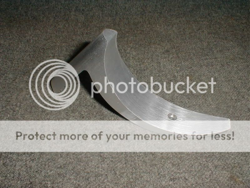
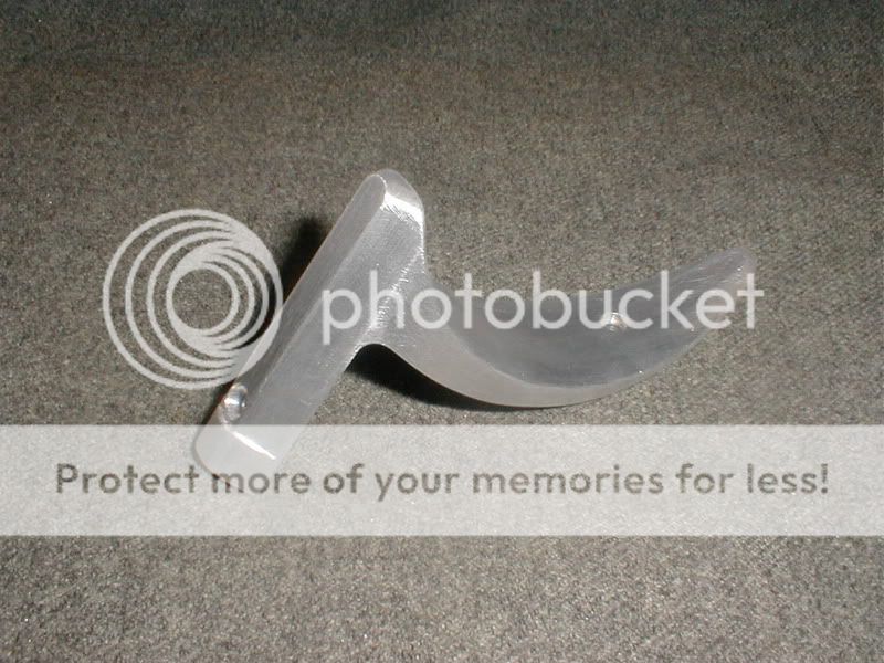
 | Here's the lever cut from 3/8" O-1. I need to contour the outside and heat treat it. |
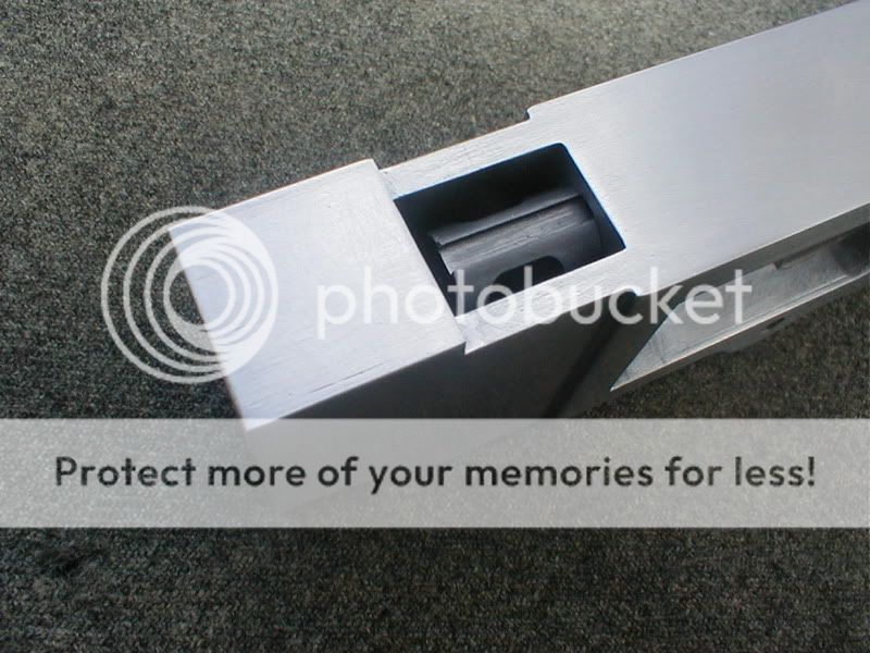
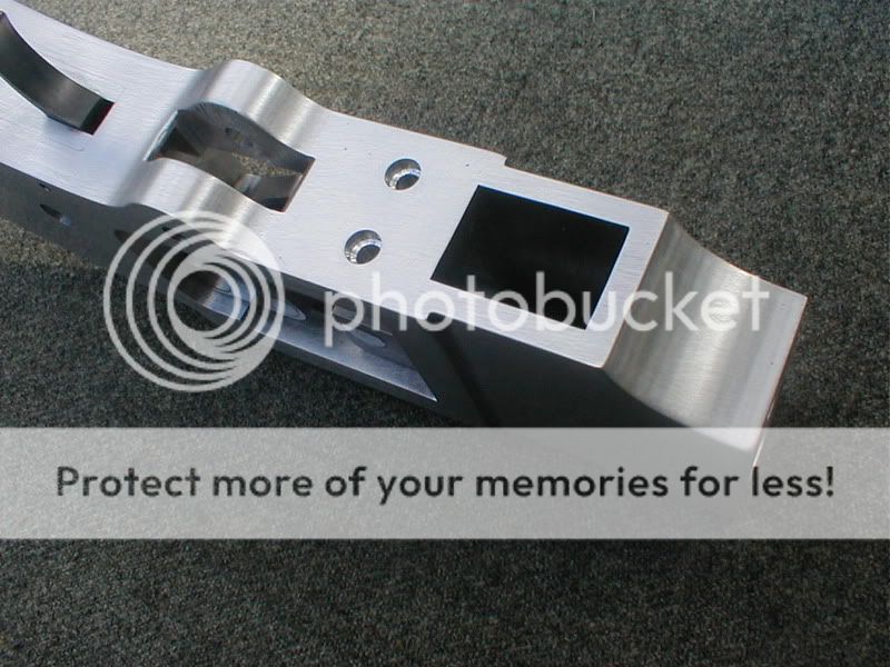 | Remember that block of aluminum that we broached that hole in? Well, here it is shown from the bottom side. |
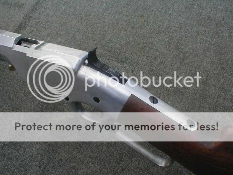
 | Here are the stock tangs showing the hammer spring installed. This spring is adjustable for tension from the outside. This is a hold over from the Volcanic Pistol which had a lever manipulated by a single finger, the idea was to have the spring adjusted just hard enough to bust the primer, and still be light enough to operate with a single finger. |
 | Here is a view of the frame from the top. You can see the front of the bolt, which is still needing an extractor. |
 | Here is a side view of the frame showing the bolt, toggle links, trigger and hammer with it's spring installed. |
 | Remember that cartridge pusher I told you I had built again but prettier? Here it is. I bored a piece of aluminum bronze on the lathe, then turned both ends leaving a flange where the thumb tab wants to be. I then took it to the mill and brought to the condition shown. I used a 3/4" end mill to make the concave face and used a 1/8" end mill to notch each side leaving the neck for the tab. The rest of it was done manually with a file. |
 | Here is the trigger spring. I cut this baby out of a "band saw blade" using tin snips. The hole was drilled with a carbide drill. |
 | Here are some lever springs. These were milled out of O-1 tool steel. I hardened them with a torch by heating them up to a straw color (which is a dirty yellow) then quenching them in oil. I then went back and heated the base end (threaded hole) to a dull red, and let air cool. That threaded hole is #6-48. |
 | Remember that Trigger? Here it is, fresh off the milling machine. See how I held it while cutting it out. |
 | Here she is starting to look like a rifle. I have already shot it as it is. I could not check for accuracy because the rear sight is not yet made. I chronographed a 140 grain Bullet in front of 3.5 grains of "Power Pistol" at around 920 FPS, - - I like it. Now, she is not yet able to load herself, or extract the fired case, so I will be working on that next. When I get er where she can shuffle, shoot, and shuck, I will then start on the butt stock. I will not contour the action or lever until I get the butt stock made and installed. That lever will not go back to a machine. From here on out, it will be contoured with a file and emery cloth. A typical steel for Flat Springs is AISI 1075, this is a cheep, high carbon steel. O-1 is an expensive, high alloy and typically not used for the lowly spring. The modulas of elasticity is about 30 million for both steels, so, yes, O-1 makes a good, though expensive spring. You are right, those springs are stout, I may thin them up a bit. It only takes one of them to keep that lever tightly closed. Go back to the other group and notice the rifle and pistol (which uses the same spring) are "Navy Brass Frames", this one is "Aluminum". That's the reason for more than one spring. So I am building three of these Volcanics at the same time. I did cut that trigger out on my little home built "CNC Mill", I can do it on a manual mill with a rotary table but it would take a full day to make just one. If I use my CNC, I can make 6 or 8 of um in the same time, and they will all be just alike. Every thing I do, I can do on a manual machine. That CNC (which I built using manual machines) makes repeat work much easier and faster. I will probably use that little CNC for about 30% of this build. Those toggle links were all manual work. The frame will go back in the mill and get recesses cut for the side plates. After side plates are fitted, it will go back to get large, 45º chamfers cut down both sides at the top. from there, everything else will be done manually. |
 | This is the rear view of the cartridge lifter. This thing rides up and down in that square hole we mortised earlier on. |
 | This is the front view. |
 | Got that extractor made, here she is, installed on the bolt and hooked over the rim of a cartridge. Notice that cartridge is sticking out the breech .150 thousandths, I did it like this so my short bolt travel would completely extract the cartridge. |
 | Here is a side view showing that lever spring very clearly. |
 | Here she is opened up. Notice that lever spring is now flexed nicely. Also notice that lifter arm has picked up the cartridge elevator. |
 | Here is the right hand side showing the lifter spring, it is different than the lever spring in that it has a bead across the front which holds the lifter up or down what ever the condition requires. |
 | Here is the lifter. Notice those 2 notches on the top, this is so the lifter spring will either hold it up, or down, while the lever is doing it's thing. That is a 1/4" ball on the end of the arm. This lifter is made from O-1 tool steel and hardened. |
 | Here's the lever showing how the lifter fits in. Mechanically, this rifle is finished. It will shuffle, shoot, and shuck, like any self respecting lever gun. The next thing I will do is mill the sides for the side plates, then I will make and fit the side plates. The next thing after that is the butt plate, then I will fit up the stock. Contouring and radiusing all those square corners, finishes up the rifle. The only thing left after that is a rear sight and bluing it. |
 | Here she is, shucking a cartridge. Go back and notice the bolt has recesses cut on both sides of the nose. Notice the cartridge elevator has 2 vertical bosses left in the trough. She works like this; when the bolt is withdrawn, extracting the cartridge, at the very last part of the lever throw, the cartridge elevator comes up from underneath, these 2 bosses kick the shell out of the action. There is a fresh cartridge laying in the bottom of the cartridge elevator. The elevator spring will hold the cartridge elevator in it's top position. When the lever is brought home, the bolt goes forward pushing the new cartridge in the chamber. Toward the end of the lever throw, the bolt is forward and the toggle links are going over center, at the very last part of the lever travel, the lifter arm pulls the cartridge elevator down. Those 2 bosses come down through the 2 recesses cut on the sides of the bolt nose. Here, the cartridge elevator accepts another cartridge, and the rifle is locked, loaded, and cocked, ready to fire. |
 | Here I'm cutting the recesses for the side plates. Those dove tails are 12.5º, this duplicated the original Volcanics and the Henry. |
 | Here I'm using .125" diameter rods to measure the dovetails. |
 | The recesses are finished. The next thing will be the side plates. |
 | I used the same cutter that I used to cut the recesses, to cut the ends of the side plates. That way the angles would be identical. My side plates are 2.312" long, I read where the original Volcanic's were 2.4" long. These side plates want to be about 1 to 2 tenth's larger than the recesses, making for a light press fit. Use both thumbs to push the plates in and out. I got lucky and did a good job here on the fit. |
 | Here is the right hand side plate installed. |
 | The left hand side plate. |
 | Here I have the "Volcanic" butt plate profiled out. There is a lot of work yet to be done on this baby, but we got a good start. |
 | About that butt plate, this is a project in it's self. Here I have made a fixture to grind the elliptical cross section (looking at em from the back). |
 | OK, we almost there. The only thing left is to mill a partial octagon on the top and contour the back. |
 | Finished. |
 | The wood is fitted to the metal, and the metal is fitted to the wood. Now, we need to make em round and purty. |
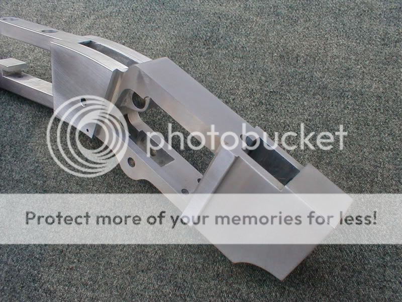
 | The receiver is finished with the exception of a dove tail for the rear sight. |
 | Another angle. |
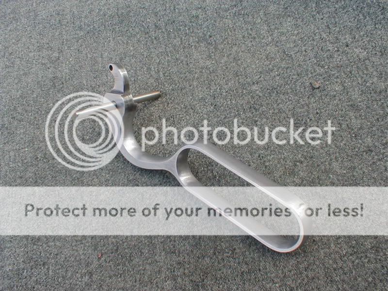 | Here is that square and blocky lever after 5.5 hours of filing and polishing. |
 | Here is the hammer and lever screws. These were made from O-1 tool steel and quenched in oil. I then polished them and fire blued em. I let the fire blue process remove the brittleness, sort of like killing two rocks with one bird. These are custom #10-32's. |
 | I made it round and purty. |
 | The butt. |
 | Another angle. |
 | Remember I said the "Henry" was an enlarged "Volcanic"? See what I mean. |
 | It's a sight. |
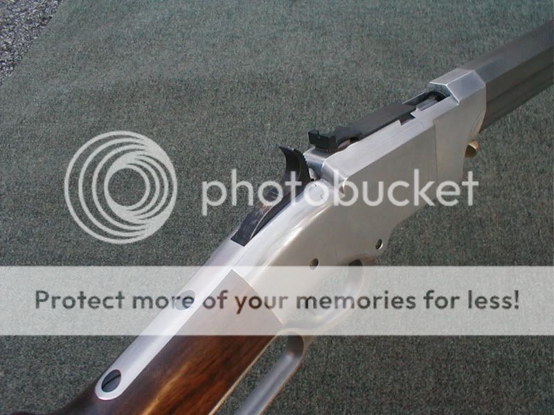 | Sight installed. Yeah, that is the way they did it. After doing it, it was learned that this kind of sight (notch) did not work very well this close to the eye. It was then moved to the barrel. A peep sight would have been just the ticket here. |
 | Finished! |
I plan to leave the receiver it's natural color to mimic the silver plated brass ones that were offered for an additional $5.00! I would have hard anodized it except the side plates would no longer fit. The anodizing adds dimension to the parts, and they were very close to began with. I could have made them smaller, and the anodizing bring them to size, but that is a guessing game.
I know it's a lot of trouble making custom cartridges for this baby but I'm delighted with the way it shoots. That big 40 caliber bullet comes out of that barrel at a little over 900 FPS giving me about 280 foots pounds of energy. The recoil is very mild, and so is the noise. I don't feel the need for hear protection. I have shot it several times inside my closed garage!
She weighs about 5 pounds and 4 ounces, but she will hold 21 cartridges, and that will add appreciable to the carrying weight.
Charlie says about himself and his project,
I am a mechanical engineer and machine designer. I was a machinist a long time ago. I have a "Bridgeport" and a "1955 Tool Room Hendy". I also have a small, but very robust "CNC Tabletop Mill", which I built myself.
I started trying to figure out how to do a modern Volcanic seven or eight years ago. I have gone through 5 or 6 different designs for the mechanism, spent nearly a year learning and making a 40 caliber barrel, I mean doing the rifling and all. I still can not do a long barrel (over 8") so I had to use a blank here. Since I am not doing this for profit, I don't worry about time at all. Those 2 screws ( hammer and lever) cost me about 4 hours, design machining, and heat treating. And that's just 2 silly little screws that you think I would purchase at a hardware store for less than 2 bucks! So here I have 4 hours invested in 2 screws, at 65 or 75 dollars an hour (standard machine shop time) dem babys are expensive! Take a drawing of these 2 screws to a job shop, you already have the design, all the man has to do is purchase the material and machine them out, then heat treat em. Tell him you don't want any favors, tell him to charge his standard rate, see what he says!
You gotta love it man, if you don't, you will never invest this time and effort. How much time? It's a life style man.
Now I am a pretty good machinist, and I can compete with professional machinist in the time it takes to make a part, but then I am the one who designed that part. How long was I thinking about what that part would look like, and how would I make it? It would take appreciable time to go back and estimate the time, and materials and design for each part. I would much rather take this time required to estimate, and make some more parts. So what would I charge to make this gun for some one else? At this time, I would not take such a commission.


8 comments:
That Charlie is something else.
If I were to build a rifle, I'd start with the action, add a barrel, add the magazine...
He starts with the front sight.
Back in the '90s I published a graphic novel called DEMON GUN, whose hero carried a Volcanic pistol modified to fire Henry rifle cartridges. The comic was optioned, and I've always dreamed that if it ever became a movie I'd find someone like Charlie to build me a "Thunderer" (the gun's name in the comic).
You're a true artist, Charlie, and you Volcanics are just beautiful. Let me know if I can send you a copy of Demon Gun. It would be my pleasure and honor to do so.--GC
(that would be...YOUR Volcanics...)
Charlie I have tried to find diagrams and prints or schematics for the rifle and have come up dry. I would like to build one as well. Some helpon plans would be great. I am going to the NRA museum in Cody this summer. maybe I can find something there. thanks Denny Anders dennisanders01@comcast.net
What an amazing hobby you have. Amazing craftsmanship and machining skills.
Isaac B.
Security Safes
Hi I just wanted to know how to make things like this on my own? I want to start making replicas for personal hobby and I just don't know where to begin. Do i have to scan images and measure out on screen or something? Do i have to own the gun i want to re create or? I am just confused.
How much would it cast to get a volcanic rifle and pistol made
I used to think I was a machinist, until in recent years I have began studying to be a gun smith. Today I am somewhat humbled on both counts. Excellent redesign and rendition on your part. This is art. Speaking of which, it wouldn't surprise me if you had a set of engraving tools hidden in your back pocket as well.
Post a Comment